المنتجات الأساسية

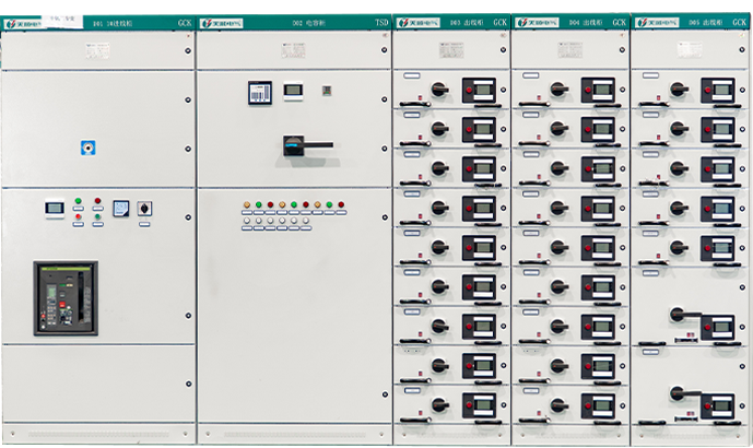
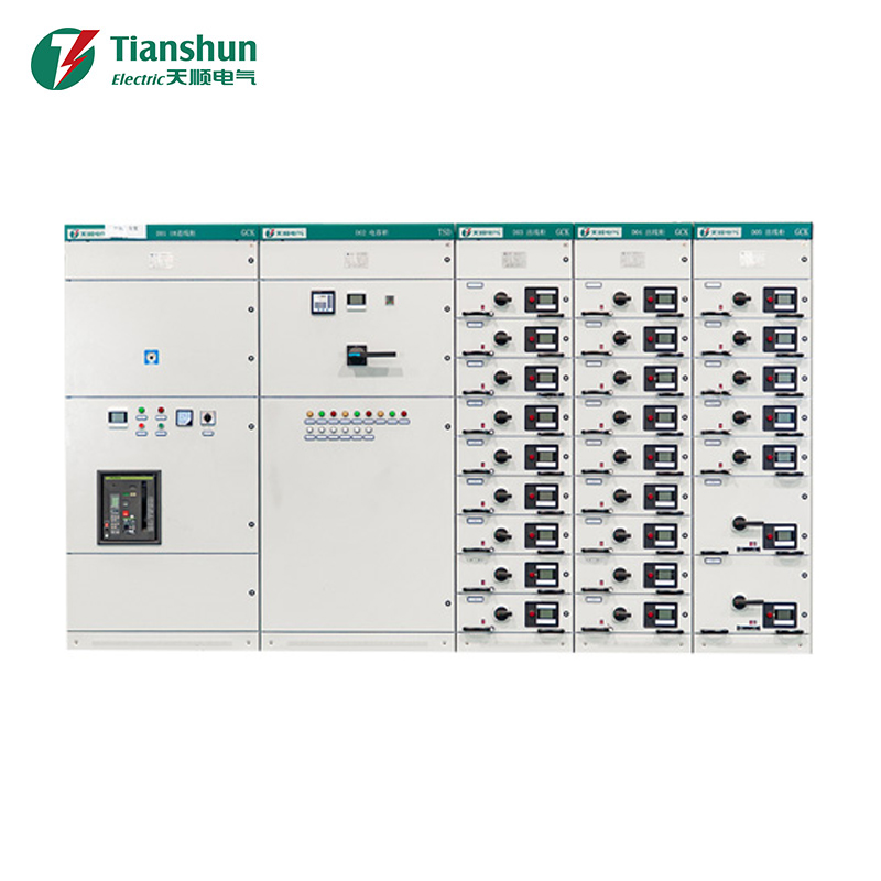
جي سي كيه

الفئات الشعبية

عرض المزيد
  • Ningbo Tianshun Electric Co., Ltd
  • Ningbo Tianshun Electric Co., Ltd
  • Ningbo Tianshun Electric Co., Ltd

نبذة عن الشركة

تعزيز التقدم من خلال حلول كهربائية موثوقة وذكية.

شركة Tianshun Electric هي مؤسسة متخصصة في البحث والتطوير والإنتاج والمبيعات لمعدات التوزيع الكهربائي ذات الجهد العالي والمنخفض والمنتجات الكهربائية الذكية. يمتلك فريقنا خبرة تزيد عن 20 عامًا في مجال نقل وتوزيع الطاقة، حيث نجمع بين الخبرة الهندسية المتقدمة والإدارة الفعالة لتقديم دعم فني شامل طوال دورة حياة المنتج بالكامل—بدءًا من التركيب والتشغيل، مرورًا بالصيانة والتدريب، وصولًا إلى الترقيات النظامية. يلتزم فريق خدمة ما بعد البيع المحترف لدينا بمبدأ "استجابة سريعة، صيانة احترافية".
عرض المزيد
  • 0+

    خبرة الصناعة

  • 0+

    الموظفين الفنيين

  • 0+م²

    منطقة المصنع

  • 0ساعات

    الاستجابة في الوقت المناسب

نظام الطاقة
في محطات الطاقة والمحطات الفرعية وشبكات النقل والتوزيع، تُستخدم مجموعات المفاتيح الكهربائية ذات الجهد العالي والمنخفض لدينا لتوزيع الطاقة وحماية الدوائر وعزل الأخطاء، مما يضمن تشغيل الشبكة بشكل آمن ومستقر. تتميز منتجاتنا بالموثوقية العالية والمراقبة الذكية وقدرات التشغيل عن بعد، وهي مناسبة لمستويات الجهد المختلفة من 10 كيلو فولت إلى 35 كيلو فولت.
عرض المزيد
التصنيع الصناعي
في مصانع الصلب والآلات والسيارات والإلكترونيات وغيرها من المنشآت الصناعية، توفر معداتنا الكهربائية تحكمًا موثوقًا في الطاقة وحماية لخطوط الإنتاج والمحركات الكبيرة وأنظمة الإضاءة. بفضل قدرتها العالية على تحمل الدوائر القصيرة وتصميمها المعياري، فإن منتجاتنا سهلة الصيانة والتوسع، وتلبي المتطلبات الصارمة للإنتاج المستمر.
عرض المزيد
تشييد المباني
 في المجمعات التجارية والمستشفيات والمدارس والمجتمعات السكنية، تُستخدم مجموعات المفاتيح الكهربائية ذات الجهد المنخفض لدينا لتوزيع طاقة المباني والتحكم في مضخات الحرائق وإمدادات طاقة المصاعد والتدفئة والتهوية وتكييف الهواء. بفضل هيكلها المدمج وتشغيلها الآمن ودعمها لمراقبة الطاقة الذكية، تساهم منتجاتنا في بناء كفاءة الطاقة وإدارة السلامة الكهربائية.
عرض المزيد
مواصلات
في السكك الحديدية ومترو الأنفاق والمطارات والموانئ ومحطات شحن السيارات الكهربائية، تكون معداتنا الكهربائية مسؤولة عن إمداد طاقة الجر وتوزيع الإضاءة والتحكم في الشاحن. بفضل مقاومة الاهتزازات والحماية من الرطوبة والغبار، تتكيف منتجاتنا مع بيئات النقل المعقدة، مما يضمن التشغيل الموثوق لمرافق النقل على مدار الساعة طوال أيام الأسبوع.
عرض المزيد
صناعة البتروكيماويات
في مصافي التكرير، والمصانع الكيميائية، وخطوط أنابيب النفط والغاز، تُستخدم مفاتيح التوزيع الكهربائي المضادة للانفجار ذات الجهد العالي والمنخفض لدينا في توزيع الطاقة والتحكم في المحركات داخل المناطق الخطرة. تتوافق منتجاتنا مع معايير الحماية من الانفجار، وتتميز بمقاومة التآكل، والإحكام العالي، ووظيفة الإيقاف الطارئ عن بُعد، مما يوفر ضمان أمان قوي لصناعة البتروكيماويات.
عرض المزيد
الطاقة الجديدة
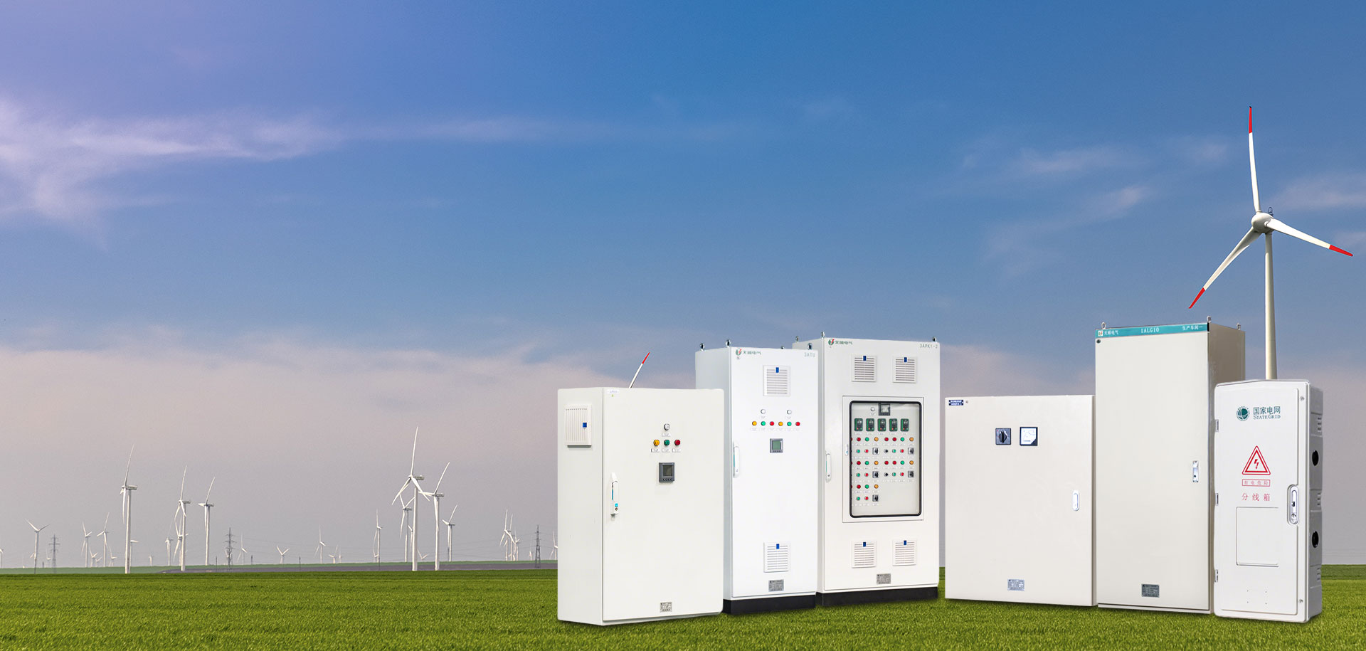
في مزارع الرياح، ومحطات الطاقة الشمسية الكهروضوئية، ومحطات تخزين الطاقة، تُستخدم معدات التوزيع الكهربائي لدينا في توزيع التيار المتردد/المستمر على جانبي النظام، وحماية ربط الشبكة، وعزل الأنظمة. تدعم منتجاتنا التبديل بالتيار المستمر، وإعادة الغلق الذكية، والتشغيل في نطاق واسع من درجات الحرارة، مما يتيح التكيف مع البيئات الخارجية القاسية، ويسهل دمج الطاقة النظيفة في الشبكة بكفاءة.
عرض المزيد
نظام الطاقة
في محطات الطاقة والمحطات الفرعية وشبكات النقل والتوزيع، تُستخدم مجموعات المفاتيح الكهربائية ذات الجهد العالي والمنخفض لدينا لتوزيع الطاقة وحماية الدوائر وعزل الأخطاء، مما يضمن تشغيل الشبكة بشكل آمن ومستقر. تتميز منتجاتنا بالموثوقية العالية والمراقبة الذكية وقدرات التشغيل عن بعد، وهي مناسبة لمستويات الجهد المختلفة من 10 كيلو فولت إلى 35 كيلو فولت.
عرض المزيد
التصنيع الصناعي
في مصانع الصلب والآلات والسيارات والإلكترونيات وغيرها من المنشآت الصناعية، توفر معداتنا الكهربائية تحكمًا موثوقًا في الطاقة وحماية لخطوط الإنتاج والمحركات الكبيرة وأنظمة الإضاءة. بفضل قدرتها العالية على تحمل الدوائر القصيرة وتصميمها المعياري، فإن منتجاتنا سهلة الصيانة والتوسع، وتلبي المتطلبات الصارمة للإنتاج المستمر.
عرض المزيد
تشييد المباني
 في المجمعات التجارية والمستشفيات والمدارس والمجتمعات السكنية، تُستخدم مجموعات المفاتيح الكهربائية ذات الجهد المنخفض لدينا لتوزيع طاقة المباني والتحكم في مضخات الحرائق وإمدادات طاقة المصاعد والتدفئة والتهوية وتكييف الهواء. بفضل هيكلها المدمج وتشغيلها الآمن ودعمها لمراقبة الطاقة الذكية، تساهم منتجاتنا في بناء كفاءة الطاقة وإدارة السلامة الكهربائية.
عرض المزيد
مواصلات
في السكك الحديدية ومترو الأنفاق والمطارات والموانئ ومحطات شحن السيارات الكهربائية، تكون معداتنا الكهربائية مسؤولة عن إمداد طاقة الجر وتوزيع الإضاءة والتحكم في الشاحن. بفضل مقاومة الاهتزازات والحماية من الرطوبة والغبار، تتكيف منتجاتنا مع بيئات النقل المعقدة، مما يضمن التشغيل الموثوق لمرافق النقل على مدار الساعة طوال أيام الأسبوع.
عرض المزيد
صناعة البتروكيماويات
في مصافي التكرير، والمصانع الكيميائية، وخطوط أنابيب النفط والغاز، تُستخدم مفاتيح التوزيع الكهربائي المضادة للانفجار ذات الجهد العالي والمنخفض لدينا في توزيع الطاقة والتحكم في المحركات داخل المناطق الخطرة. تتوافق منتجاتنا مع معايير الحماية من الانفجار، وتتميز بمقاومة التآكل، والإحكام العالي، ووظيفة الإيقاف الطارئ عن بُعد، مما يوفر ضمان أمان قوي لصناعة البتروكيماويات.
عرض المزيد
الطاقة الجديدة
في مزارع الرياح، ومحطات الطاقة الشمسية الكهروضوئية، ومحطات تخزين الطاقة، تُستخدم معدات التوزيع الكهربائي لدينا في توزيع التيار المتردد/المستمر على جانبي النظام، وحماية ربط الشبكة، وعزل الأنظمة. تدعم منتجاتنا التبديل بالتيار المستمر، وإعادة الغلق الذكية، والتشغيل في نطاق واسع من درجات الحرارة، مما يتيح التكيف مع البيئات الخارجية القاسية، ويسهل دمج الطاقة النظيفة في الشبكة بكفاءة.
عرض المزيد

الأخبار والمعلومات

  • 2026-04-08

    صيانة قواطع الدائرة ذات الجهد المنخفض

    مع التطور المستمر للعلوم والتكنولوجيا والابتكار المستمر في المواد، أصبحت آليات المعدات أكثر إحكاما ومتانة وتتمتع بعوامل أمان أعلى. تتطور المعدات الحالية نحو أنواع خالية من التفكيك والتفتيش والصيانة. فيما يلي عناصر الفحص لمفاتيح الجهد المنخفض أثناء صيانة النظام: أ. معايرة الجهد المنخفض لإغلاق قاطع الدائرة وتعثره.ب. معايرة مزامنة قاطع الدائرة.ج. اختبار مقاومة التيار المستمر الأولي.د. اختبار مقاومة العزل الأولية.هـ. اختبار تحمل الجهد الأساسي.ف. إضافة مواد التشحيم إلى آلية النقل.ز. فحص ومعايرة الصمامات.ح. فحص ومعايرة محرك تخزين الطاقة.أنا. فحص جهات الاتصال والينابيع الأولية.ج. فحص ومعايرة سرعة الإغلاق والتعثر.ك. فحص ومعايرة الدوائر الثانوية والمفاتيح المساعدة وجهات الاتصال.
    Ningbo Tianshun Electric Co., Ltd
  • 2026-04-08

    صيانة مفاتيح السكاكين

    أ. فحص نقاط اتصال الشفرات الثابتة والمتحركة.ب. فحص نوابض تلامس الشفرة.ج. فحص المسامير المحورية.د. معايرة مواضع الإغلاق والفتح.هـ. فحص ومعايرة آلية النقل.ف. معايرة مقاومة العزل من طور إلى طور ومن طور إلى أرض.
    Ningbo Tianshun Electric Co., Ltd
  • 2026-04-08

    صيانة قواطع الدائرة الهوائية الأوتوماتيكية

    تعتبر قواطع الدائرة الهوائية الأوتوماتيكية أكثر تعقيدًا من الناحية الهيكلية من الموصلات والمشغلات المغناطيسية لأنها تحتوي على جهاز إطفاء قوس كامل نسبيًا. يمكنهم إيقاف تشغيل الدائرة تلقائيًا في حالة التحميل الزائد أو ماس كهربائي أو انخفاض الجهد أو فقدان الجهد. أ. اختبار الإغلاق والتعثر.ب. إضافة مواد التشحيم إلى آلية النقل.ج. معايرة مقاومة العزل من مرحلة إلى مرحلة.د. معايرة التيار الزائد للمفتاح.هـ. فحص جهات الاتصال الواردة والصادرة.ف. فحص شبكة إطفاء القوس.ز. صيانة الاتصال.
    Ningbo Tianshun Electric Co., Ltd
  • 2026-07-31

    What is the difference between HV and MV switchgear?

    HV and MV Switchgear Differ Mainly in Voltage Class, Insulation Method, and Physical Scale The core difference between HV and MV switchgear is the voltage range each is built to handle: high-voltage switchgear is engineered for systems rated above 72.5 kV, sometimes reaching hundreds of kilovolts at transmission substations, while medium-voltage switchgear typically covers the 1 kV to 72.5 kV range used in distribution networks and industrial power systems. This voltage gap drives nearly every other design difference: insulation clearances, arc-quenching technology, cabinet size, current-carrying capacity, and even how the equipment is transported and installed. The sections below break down these distinctions point by point, cover typical construction details, and explain how to match the correct switchgear class to your project's actual voltage and fault current requirements. Voltage Classification: Where HV Starts and MV Ends Voltage class is the defining boundary between these two switchgear categories, and it is set by widely referenced international standards rather than by manufacturer preference. Understanding this boundary matters because it determines which safety codes, testing protocols, and physical clearance requirements apply to a given installation. 1Medium-voltage switchgear generally spans 1 kV to 72.5 kV, commonly seen at 11 kV, 24 kV, and 36 kV in distribution substations, industrial plants, and commercial buildings with heavy electrical loads. 2High-voltage switchgear begins above 72.5 kV and extends through common transmission levels such as 110 kV, 220 kV, and beyond, depending on the grid it serves and the transformer capacity it protects. 3Some equipment in the 66 kV to 72.5 kV band is referred to differently depending on regional grid classification standards, so always confirm the rated voltage against the specific system, not just the switchgear label printed on a datasheet. Side-by-Side Comparison of Key Technical Parameters Beyond the voltage threshold itself, HV and MV switchgear diverge in insulation clearance, arc energy, and physical footprint. The table below summarizes the parameters most relevant to specification and procurement decisions when comparing high-voltage switchgear against its medium-voltage counterpart. Comparison of typical HV and MV switchgear technical parameters Parameter MV Switchgear HV Switchgear Rated Voltage Range 1 kV to 72.5 kV Above 72.5 kV Insulation Method Air, vacuum, or SF6 Primarily SF6 gas-insulated (GIS) Typical Rated Current 630 A to 3150 A 1250 A to 8000 A Short-Circuit Breaking Capacity 16 kA to 31.5 kA 31.5 kA to 63 kA Physical Footprint Compact indoor panels Larger, often outdoor bays Common Application Distribution substations, factories Transmission substations, grid interconnection Why Insulation and Arc-Quenching Technology Differ So Much The physics of interrupting current at higher voltage is what forces high-voltage switchgear into a fundamentally different construction than its medium-voltage counterpart. As voltage climbs, the energy released during arc formation at the moment of switching grows substantially, and the equipment must be built to contain and extinguish that arc safely within milliseconds. Gas-Insulated Switchgear (GIS) at High Voltage Most high-voltage switchgear above 72.5 kV relies on sulfur hexafluoride (SF6) gas insulation sealed within metal enclosures. SF6 has excellent dielectric strength and arc-quenching properties, which allows the equipment to interrupt large fault currents in a much smaller physical envelope than air-insulated alternatives would require at the same voltage. This is why compact GIS bays have largely replaced older open-air high-voltage yards in space-constrained substations. Vacuum and Air Insulation at Medium Voltage Medium-voltage switchgear more commonly uses vacuum interrupters or air-insulated designs, since the lower voltage and current levels do not require SF6's extreme dielectric performance, allowing for simpler maintenance and lower long-term gas handling costs. Vacuum circuit breakers in particular have become the dominant technology at MV level due to their long mechanical life and minimal need for routine servicing. Insulation Clearance and Creepage Distance Air clearance and creepage distance requirements scale directly with rated voltage. A high-voltage switchgear bay rated at 220 kV typically requires several times the phase-to-ground clearance of an 11 kV medium-voltage panel, which is one of the main reasons HV installations occupy so much more physical space even before accounting for the switchgear housing itself. Where Each Switchgear Class Is Actually Used Matching switchgear class to the correct point in the power network avoids both overspending on unnecessary capability and underspecifying equipment that cannot handle the actual fault current present. Transmission substations rely almost exclusively on high-voltage switchgear to connect long-distance power lines and step-down transformers to the grid at points where fault currents can reach tens of thousands of amperes. Utility distribution networks use medium-voltage switchgear to route power from substations to local feeders serving neighborhoods and commercial zones, typically operating at 11 kV to 35 kV. Heavy industrial plants such as steel mills, chemical facilities, and data centers typically use MV switchgear internally, stepped down from an HV grid connection point at the plant boundary. Renewable energy interconnection points, including wind and solar farms, frequently require high-voltage switchgear at the grid tie-in, with MV switchgear used further downstream at the collection level between turbines or panel arrays. Rail and metro traction power systems often combine both classes, using HV switchgear at the bulk supply point and MV switchgear to feed traction substations along the line. Installation, Space, and Maintenance Considerations Beyond raw electrical performance, HV and MV switchgear present very different practical demands during installation and over their service life, and these differences often influence project cost and schedule as much as the equipment price itself. High-voltage switchgear bays often require dedicated outdoor yards or large indoor halls due to insulation clearance requirements and equipment size, along with foundation work rated for significant equipment weight. Medium-voltage switchgear panels are commonly installed indoors in compact substation rooms, sometimes stacked in a lineup within a fraction of the space HV equipment would need for the same number of feeder circuits. Routine maintenance on GIS-based high-voltage switchgear focuses heavily on gas pressure monitoring and leak detection, while MV switchgear maintenance more often centers on contact wear, mechanism lubrication, and periodic insulation resistance testing. Commissioning timelines for high-voltage switchgear are typically longer, since on-site assembly, gas filling, and high-voltage testing require specialized crews and equipment not needed for factory-assembled MV panels. Transport logistics also differ meaningfully: large HV switchgear bays are frequently shipped in sections and assembled on site, whereas MV switchgear panels are more commonly delivered as factory-assembled, type-tested units ready for direct installation with minimal on-site work beyond cable termination. A Practical Checklist for Choosing Between HV and MV Switchgear Before finalizing a switchgear specification, running through the following checklist helps confirm the correct voltage class and configuration for the project. CheckConfirm the actual system operating voltage and available fault current at the connection point, not just the nominal grid voltage listed in planning documents. CheckEvaluate available installation space, since high-voltage switchgear generally demands significantly more clearance than medium-voltage panels, especially for air-insulated designs. CheckReview long-term maintenance capacity, particularly for SF6 gas handling if selecting GIS-type high-voltage switchgear, since gas monitoring requires trained personnel. CheckVerify that the selected switchgear carries type-test certification matching the relevant international insulation and short-circuit standards for its voltage class. CheckAssess future load growth expectations, since undersized MV switchgear at a site with planned expansion may require costly early replacement. Common Misconceptions Worth Clearing Up A few misunderstandings come up repeatedly when engineers and buyers compare HV and MV switchgear for the first time, and clearing them up early can prevent specification errors later in a project. "Higher Voltage Always Means Higher Current" This is not necessarily true. Voltage and current ratings are specified independently based on the power being transferred, and a high-voltage switchgear unit is not automatically rated for a higher current than a medium-voltage panel; some MV panels handle very high currents at lower voltage for high-power industrial loads. "GIS Is Only Used for High Voltage" While SF6 gas-insulated designs dominate the high-voltage switchgear category, some compact medium-voltage switchgear products also use gas insulation to reduce footprint in space-constrained urban substations, so insulation method alone is not a reliable way to distinguish HV from MV equipment. Summary: Voltage Class Decides Everything Else In short, the difference between HV and MV switchgear starts with rated voltage but extends into insulation technology, physical size, maintenance routines, and where each type sits in the power network. High-voltage switchgear serves transmission-level connections above 72.5 kV and typically relies on SF6 gas insulation to manage extreme dielectric and interrupting demands, while medium-voltage switchgear handles distribution and industrial power in a more compact, often air- or vacuum-insulated format. When specifying equipment for a substation or industrial power project, matching the switchgear class precisely to the system's actual voltage, fault current, and installation space avoids both unnecessary cost and dangerous underspecification, making this comparison one of the most important early decisions in any electrical distribution project. For buyers comparing suppliers of both high-voltage switchgear and medium-voltage switchgear, requesting documented type-test reports, short-circuit ratings, and gas or vacuum interrupter service intervals provides a more reliable basis for comparison than catalog specifications alone, since these details determine how the equipment will actually perform under real fault conditions over decades of service. table tr:hover td { background-color: #dcefe3 !important; transition: background-color 0.2s ease; } ol li::marker { color: #0F8A5C; }
    Ningbo Tianshun Electric Co., Ltd
  • 2026-08-07

    High-Voltage Switchgear Guide: Powering Safe Transmission High Voltage Networks

    What High-Voltage Switchgear Does for Transmission High Voltage Systems The direct answer is this: high-voltage switchgear is the equipment responsible for switching, isolating, and protecting transmission high voltage circuits from overload, short-circuit faults, and unsafe operating conditions. Without it, transmission high voltage networks would have no reliable way to interrupt fault currents, which can exceed tens of thousands of amperes in a matter of milliseconds. Every substation, generation plant, and long-distance transmission corridor depends on high-voltage switchgear as the primary control layer between power sources and the grid. In practical terms, high-voltage switchgear combines circuit breakers, disconnectors, earthing switches, current transformers, and protection relays into a single coordinated system. This system allows operators to safely energize or de-energize sections of a transmission high voltage line, isolate equipment for maintenance, and clear faults before they cascade into wider blackouts. Utilities and industrial power users alike rely on this equipment because a single uncontrolled fault on a transmission high voltage line can damage transformers, generators, and connected loads within seconds. How High-Voltage Switchgear Protects and Controls the Grid High-voltage switchgear performs three interconnected functions within any transmission high voltage system: switching, isolation, and protection. Understanding how each function operates explains why switchgear reliability is treated as a non-negotiable design requirement by grid operators. Switching Function Circuit breakers inside high-voltage switchgear open and close under load, redirecting power flow across transmission high voltage lines without interrupting service to unaffected sections of the network. Isolation Function Disconnectors and earthing switches within high-voltage switchgear create a visible, physical break in the circuit, allowing maintenance crews to work safely on de-energized transmission high voltage equipment. Protection Function Protection relays paired with high-voltage switchgear detect abnormal current or voltage patterns and trigger breaker tripping within 2 to 5 cycles, typically under 100 milliseconds, to limit fault energy and prevent equipment destruction. Key Types of High-Voltage Switchgear Used in Transmission Applications Not all high-voltage switchgear is built the same way. The choice between designs depends on voltage class, available footprint, environmental exposure, and maintenance strategy. The table below summarizes the most common configurations found in transmission high voltage installations. Comparison of common high-voltage switchgear configurations for transmission networks Switchgear Type Typical Voltage Range Insulation Medium Best Suited For Air-Insulated Switchgear (AIS) 72.5 kV – 550 kV Open air Large open-air substations with abundant space Gas-Insulated Switchgear (GIS) 72.5 kV – 1100 kV SF6 or eco-friendly gas mixtures Compact urban substations, coastal or high-pollution sites Hybrid Switchgear 72.5 kV – 245 kV Mixed gas and air modules Retrofit or expansion projects with limited space For most new transmission high voltage projects above 245 kV, gas-insulated switchgear has become the preferred solution because it reduces substation footprint by up to 70 percent compared with air-insulated designs, while offering superior protection against contamination and moisture ingress. Critical Technical Specifications to Evaluate Before Selecting High-Voltage Switchgear Selecting high-voltage switchgear for a transmission high voltage project is not a one-size-fits-all decision. Engineers should verify the following parameters against project requirements before finalizing equipment specifications. Rated voltage and insulation level, matched to the nominal system voltage plus an appropriate safety margin Rated short-circuit breaking current, generally specified between 31.5 kA and 63 kA for major transmission high voltage substations Rated normal current, which determines continuous thermal capacity under full load Mechanical and electrical endurance class, indicating how many operating cycles the switchgear can perform before service Ambient temperature range and altitude correction factors for the installation site Seismic withstand rating, particularly important for substations located in active fault zones Overlooking any single specification can lead to premature failure or costly retrofitting. A common industry benchmark requires high-voltage switchgear to achieve a design life of at least 30 years under normal operating conditions, so specification accuracy at the procurement stage has long-term financial consequences. Installation and Maintenance Best Practices for Transmission High Voltage Switchgear Proper installation and a disciplined maintenance schedule extend the operational life of high-voltage switchgear and reduce unplanned outages across transmission high voltage networks. Installation Guidelines Site preparation must account for grounding grid resistance, foundation load capacity, and clearance distances defined by the applicable voltage class. Gas-insulated high-voltage switchgear additionally requires strict gas-handling procedures during commissioning to avoid moisture contamination inside sealed compartments. Maintenance Guidelines Routine inspection intervals for high-voltage switchgear typically follow a 12-month visual inspection cycle and a 3 to 6 year detailed maintenance cycle, depending on operating conditions and manufacturer recommendations. Key checks include contact resistance measurement, SF6 gas density verification, mechanism lubrication, and protection relay calibration testing. Monitor gas pressure and density trends to detect leaks before they affect dielectric strength Perform contact resistance testing to identify wear before it causes overheating Verify trip and close timing to confirm mechanical operation remains within tolerance Inspect insulation surfaces for tracking, contamination, or partial discharge activity Common Failure Modes and How Design Choices Prevent Them Understanding why high-voltage switchgear fails helps engineers select equipment and maintenance strategies that minimize risk on transmission high voltage networks. Typical failure causes in high-voltage switchgear and corresponding preventive design measures Failure Cause Effect on Transmission System Preventive Measure Contact overheating Localized insulation degradation, potential fire risk Silver-plated contacts, regular resistance testing SF6 gas leakage Reduced dielectric and interrupting capability Sealed pressure system monitoring, leak detection sensors Mechanism sticking Delayed or failed breaker tripping during a fault Scheduled lubrication, spring-charge motor inspection Insulation contamination Flashover risk, unplanned outage Enclosed gas-insulated design, periodic surface cleaning Statistics gathered across the utility industry consistently show that the majority of switchgear failures stem from mechanical wear rather than electrical insulation breakdown, which reinforces why mechanical maintenance schedules deserve equal attention to electrical testing programs. Choosing a Reliable High-Voltage Switchgear Solution for Transmission Projects When evaluating a supplier of high-voltage switchgear for a transmission high voltage project, engineers and procurement teams should look beyond price and confirm manufacturing quality, type-test certification, and after-sales support capability. Equipment that has passed internationally recognized type tests for short-circuit breaking, temperature rise, and mechanical endurance offers a much lower long-term risk profile than uncertified alternatives. Our high-voltage distribution equipment lineup covers air-insulated, gas-insulated, and hybrid switchgear configurations engineered to meet the demanding operating conditions of transmission high voltage networks, from coastal substations to high-altitude installations. Each unit is designed with serviceability in mind, allowing maintenance teams to perform inspections and component replacement without extended downtime. Project teams planning a new substation or retrofit can review detailed specifications, voltage classes, and configuration options on our high-voltage distribution equipment product page, where technical documentation supports side-by-side comparison against project requirements. In summary, high-voltage switchgear remains the single most important protective layer within any transmission high voltage network, and its selection deserves the same engineering rigor applied to transformers, transmission towers, and conductor design. A well-specified, properly maintained switchgear system directly translates into fewer outages, lower lifecycle costs, and a safer operating environment for both personnel and equipment.
    Ningbo Tianshun Electric Co., Ltd
  • 2026-08-14

    How Much Voltage Is in Power Lines?

    The Direct Answer To How Much Voltage Is In Power Lines Power lines carry voltage that ranges from as low as 120 volts inside a home to as high as 765,000 volts on the largest long distance transmission towers. The exact number depends entirely on which stage of the grid the line belongs to. Transmission lines that move electricity from a power plant across a region typically carry between 69,000 and 765,000 volts, while distribution lines that bring power into neighborhoods usually carry between 4,000 and 35,000 volts. Once power reaches a building, transformers step the voltage down further to the 120 or 240 volts used by household outlets. This wide range exists because voltage is chosen based on distance, load, and cost. Higher voltage allows electricity to travel further with less energy loss, while lower voltage is safer and more practical for daily use inside homes and businesses. Voltage Levels Across The Grid The table below breaks down typical voltage ranges at each stage of the electrical grid, based on common utility engineering standards used across North America and much of Asia and Europe. Typical voltage ranges by grid segment, based on common utility standards Grid Segment Typical Voltage Range Common Use Generation Output 11,000 to 25,000 volts Voltage produced directly at the power plant Bulk Transmission Lines 230,000 to 765,000 volts Long distance movement across states or regions Sub-Transmission Lines 69,000 to 138,000 volts Moving power to local substations Primary Distribution Lines 4,000 to 35,000 volts Feeding neighborhoods and commercial areas Secondary Distribution Lines 120 to 480 volts Direct connection to homes and small buildings Transmission Lines Versus Distribution Lines What Sets Them Apart Transmission lines and distribution lines look different and serve different jobs. Transmission lines run on tall steel lattice towers, often exceeding 100 feet in height, and carry electricity across long stretches of open land. Distribution lines run on shorter wooden or concrete poles found along streets, and they carry electricity the final few miles to homes and businesses. Transmission lines minimize energy loss over long distances by using very high voltage Distribution lines operate at a lower voltage since they cover shorter distances within a city or town Transmission towers are usually spaced hundreds of feet apart with wide clearance below Distribution poles are spaced much closer together and are far more common in residential areas The Role Of High-Voltage Distribution Equipment Before electricity reaches a home, it passes through several pieces of High-Voltage Distribution Equipment that manage the transition from transmission level voltage down to a level that homes and businesses can safely use. This equipment forms the backbone of the local grid and includes the following components. Step-Down Substations Substations reduce transmission voltage down to distribution voltage, often bringing hundreds of thousands of volts down to a range near 12,000 volts. Distribution Transformers Mounted on poles or placed on pads at ground level, these units make the final reduction from primary distribution voltage down to the 120 or 240 volts used indoors. Reclosers And Switches These devices detect faults on the line and interrupt power automatically, then attempt to restore it, reducing how long an outage lasts. Voltage Regulators Placed along longer distribution feeders, regulators keep voltage steady as demand rises and falls throughout the day. Factors That Determine How Much Voltage A Line Carries Distance Traveled The farther electricity needs to travel, the higher the voltage tends to be. Moving power over hundreds of miles at low voltage would waste enormous amounts of energy as heat, so utilities raise voltage for long stretches and lower it again closer to the point of use. Population And Load Density Areas with dense populations and heavy commercial or industrial demand often use higher distribution voltages, such as 25,000 or 35,000 volts, compared to lighter residential areas that may use 4,000 to 13,000 volts. Local Utility Standards Every utility company sets its own preferred voltage classes based on its equipment history, regional terrain, and cost planning. This is why voltage on a distribution line in one city can differ from a nearby city even though both feel similar to residents. The Path Voltage Takes From Plant To Plug Electricity leaves the power plant at roughly 11,000 to 25,000 volts A step-up transformer raises it to transmission level, often 230,000 volts or higher The line travels across the region toward a regional substation A step-down substation lowers voltage to sub-transmission level, near 69,000 to 138,000 volts A local substation reduces it further to primary distribution voltage, typically 4,000 to 35,000 volts A pole mounted or pad mounted transformer makes the final drop to 120 or 240 volts for indoor use Why Voltage Level Affects Safety Distance Higher voltage lines require more clearance from buildings, trees, and people because the risk of arcing increases as voltage rises. A line carrying 500,000 volts can arc across several feet of open air without direct contact, while a low voltage service line poses far less risk from a short distance away. General clearance guidance associated with different voltage classes Voltage Class Typical Minimum Clearance Under 50,000 volts About 10 feet 50,000 to 200,000 volts About 15 feet 200,000 to 350,000 volts About 20 feet Above 350,000 volts 25 feet or more These figures are general guidance rather than fixed rules, since exact clearance depends on the equipment, the surrounding terrain, and local utility practice. Frequently Asked Questions About Power Line Voltage How much voltage is in a normal neighborhood power line Most residential distribution lines running along streets carry between 4,000 and 13,000 volts, with 12,000 volts being one of the most common levels used by utilities. How much voltage is in the big towers along the highway Tall steel lattice towers usually carry bulk transmission voltage, which commonly falls between 230,000 and 500,000 volts, though some major corridors reach 765,000 volts. How does voltage get lowered before it reaches a house A small transformer, either mounted on a nearby pole or placed on a pad near the ground, makes the final reduction from distribution voltage down to the 120 or 240 volts used by household circuits. Is a higher voltage line always more dangerous Higher voltage generally increases the risk of arcing across open air, which is why clearance distances grow with voltage. Even lower voltage lines remain hazardous with direct contact, so all power lines deserve caution regardless of their voltage class. Why do some distribution lines carry higher voltage than others Utilities select distribution voltage based on how much load an area needs and how far the line must travel. Areas with heavier demand often use 25,000 or 35,000 volts, while lighter residential areas may stay near 4,000 to 13,000 volts. .vpl-article { font-family: Arial, Helvetica, sans-serif; color: #222222; } .vpl-article h2 { font-size: 22px; font-weight: bold; text-align: left; line-height: 1.4; margin-bottom: 15px; color: #008061; } .vpl-article h3 { font-size: 16px; font-weight: bold; text-align: left; line-height: 1.5; margin-bottom: 15px; color: #111111; } .vpl-article p { font-size: 16px; text-align: left; line-height: 2; margin-bottom: 15px; } .vpl-article ul, .vpl-article ol { margin-bottom: 15px; padding-left: 0; } .vpl-article li { font-size: 16px; line-height: 2; margin-bottom: 5px; } .vpl-article section { margin-bottom: 40px; } .vpl-article table { display: table; text-align: center; border-collapse: collapse; width: 100%; font-size: 16px; margin-bottom: 15px; } .vpl-article thead { display: table-header-group; background-color: #e6f3f0; } .vpl-article tbody { display: table-row-group; } .vpl-article tr { display: table-row; } .vpl-article th { display: table-cell; font-weight: bold; border: 1px solid #cccccc; padding: 8px; color: #008061; } .vpl-article td { display: table-cell; border: 1px solid #cccccc; padding: 8px; } .vpl-article caption { caption-side: bottom; font-size: 16px; margin-bottom: 12px; font-style: italic; color: #808080; } .vpl-intro { background-color: #f2f9f7; border-left: 5px solid #008061; padding: 20px; } .vpl-comparison { background-color: #ffffff; border: 1px solid #dbeee9; padding: 20px; } .vpl-equipment-cards { background-color: #f9fafa; padding: 20px; } .vpl-card-grid { display: flex; flex-wrap: wrap; gap: 15px; margin-top: 10px; } .vpl-card { flex: 1 1 220px; background-color: #ffffff; border-top: 4px solid #008061; box-shadow: 0 1px 4px rgba(0,0,0,0.08); padding: 15px; } .vpl-card h3 { margin-bottom: 8px; } .vpl-card p { margin-bottom: 0; } .vpl-factors { background-color: #f2f9f7; padding: 20px; border-radius: 4px; } .vpl-timeline { background-color: #ffffff; padding: 20px; border: 1px dashed #008061; } .vpl-safety { background-color: #fbf6ee; padding: 20px; border-left: 5px solid #b8860b; } .vpl-faq { background-color: #ffffff; border: 1px solid #dbeee9; padding: 20px; } .vpl-faq h3 { color: #008061; } @media only screen and (max-width: 600px) { .vpl-article h2 { font-size: 20px; } .vpl-article h3 { font-size: 16px; } .vpl-article p, .vpl-article li, .vpl-article table { font-size: 16px; } .vpl-card-grid { flex-direction: column; } .vpl-card { flex: 1 1 auto; } .vpl-intro, .vpl-comparison, .vpl-equipment-cards, .vpl-factors, .vpl-timeline, .vpl-safety, .vpl-faq { padding: 15px; } }
    Ningbo Tianshun Electric Co., Ltd
  • 2026-08-21

    High Voltage Line Layout Guide: Safe, Efficient Distribution Design

    The Direct Answer: How High Voltage Lines Should Be Arranged A well-planned high voltage line layout keeps conductors at safe vertical and horizontal distances from each other, from structures, and from the ground, while matching the mechanical and electrical demands of the High-Voltage Distribution Equipment connected at each end. In practical terms, this means choosing the correct conductor configuration (horizontal, vertical, or triangular), maintaining minimum air clearances based on voltage class, and coordinating span length with tower or pole strength. Utilities that follow these three fundamentals reduce flashover risk, lower maintenance costs, and extend equipment service life by a significant margin. Poor arrangement is one of the leading causes of unplanned outages in overhead networks. A conductor spaced too closely to a neighboring phase, or a line routed without accounting for wind sway, can trigger arcing events that damage switchgear, transformers, and other connected distribution assets. This article breaks down the arrangement principles, clearance figures, and integration practices that keep a high voltage corridor performing as designed. Key Layout Configurations for High Voltage Lines Three conductor arrangements dominate overhead high voltage design, and each one is chosen based on right-of-way width, terrain, and the type of High-Voltage Distribution Equipment the line will feed. The table below compares the three most common configurations used in medium to high voltage corridors. Comparison of common high voltage conductor arrangements Configuration Typical Use Case Advantage Limitation Horizontal Wide right-of-way, rural feeders Simplifies insulator maintenance Requires wider corridor Vertical Narrow urban corridors Minimizes lateral footprint Taller poles or towers needed Triangular (Delta) Mixed terrain, transmission spans Balances height and width More complex tower design Selecting the wrong configuration for the site conditions is a common design error. A vertical arrangement forced onto a wide, unobstructed rural corridor wastes tower height and increases wind loading, while a horizontal arrangement squeezed into an urban strip often violates minimum setback rules. Minimum Clearance and Spacing Requirements Clearance is the single most important variable in high voltage line arrangement. Spacing must account for conductor sag under load, wind-induced swing, and ice accumulation in colder climates. General industry practice for phase-to-phase and phase-to-ground clearance scales with voltage class: Below 33 kV: phase-to-phase spacing typically starts around 0.5 to 1 meter, adjusted for span length 33 kV to 132 kV: spacing generally increases to 1.5 to 3 meters depending on tower type Above 132 kV: spacing can exceed 4 meters, with additional margin for switching surge overvoltages Ground clearance at midspan must account for maximum conductor temperature and worst-case sag, not the clearance measured at installation These figures are general planning references and always require verification against the applicable local grid code and the manufacturer's rated clearance for the specific High-Voltage Distribution Equipment being installed on the line. Insulation Coordination and Safety Margins Arrangement and insulation coordination are inseparable. Even a correctly spaced conductor can flash over if the insulator string, arrester rating, or creepage distance is mismatched with the site's pollution level and altitude. Insulation coordination ensures that every component along the line, from the conductor to the connected switchgear, shares a consistent withstand voltage margin. Practical Coordination Checklist Match insulator creepage distance to the site pollution class (light, medium, heavy, or very heavy) Verify surge arrester rating against the maximum expected switching and lightning overvoltage Adjust clearance upward at higher altitudes, since reduced air density lowers dielectric strength Confirm that all connected distribution equipment shares a compatible basic insulation level (BIL) Integrating Layout with High-Voltage Distribution Equipment Line arrangement does not end at the tower or pole. The layout must feed cleanly into the switching stations, transformers, and metering enclosures that make up the broader High-Voltage Distribution Equipment network. Cable entry angles, busbar orientation inside the switchgear, and the physical approach of the overhead line all affect how easily the equipment can be maintained and how much stress is placed on terminations. A layout that brings conductors into a substation at a sharp angle increases mechanical stress on bushings and terminal connectors, shortening their service life. A gentler approach angle, combined with adequate slack in the drop conductors, reduces vibration fatigue and simplifies future retrofits. Design teams that plan the line route and the distribution equipment location together, rather than treating them as separate projects, consistently report fewer post-commissioning corrections. Environmental and Terrain Considerations Terrain shapes almost every arrangement decision. Sloped ground changes effective clearance at each support point, so designers often specify taller structures or shorter spans on hillsides to preserve the required ground clearance under sag conditions. Coastal or high-humidity regions typically call for wider phase spacing and higher-grade insulators to offset accelerated pollution buildup on insulator surfaces. Wind zones deserve particular attention. In areas with frequent high wind events, galloping conductors can momentarily close the gap between phases. Adding vertical offset between conductors, or installing spacer dampers, is a common and cost-effective mitigation that preserves the intended arrangement without redesigning the entire corridor. Common Layout Mistakes and Best Practices Field audits of underperforming corridors tend to surface the same recurring issues. Recognizing them early during the design phase avoids costly retrofits after commissioning. Underestimating conductor sag at maximum operating temperature, resulting in reduced ground clearance during peak load periods Placing structures at uneven spans without adjusting tension, which creates uneven sag and localized clearance violations Ignoring vegetation growth rates when setting the initial right-of-way width Failing to coordinate the line route with the maintenance access path required for the connected distribution equipment Best practice is to treat arrangement as a full lifecycle decision, not a one-time calculation. Reviewing clearance and spacing at the design stage, again during construction sign-off, and periodically through aerial or ground inspection keeps the corridor within its original safety envelope for decades. Maintenance Access and Corridor Planning A technically correct arrangement still fails in practice if crews cannot safely access it. Corridor planning should reserve space for bucket trucks, cable pulling equipment, and emergency repair vehicles alongside the electrical clearance requirements. Access roads parallel to the line reduce outage duration significantly, since crews reach the fault point without needing to cut through vegetation or cross private property. Regular thermal imaging and visual inspection of both the line and the connected High-Voltage Distribution Equipment should be built into the maintenance schedule from day one. Early detection of a loose connector or a degraded insulator at the equipment interface is far less costly than responding to a fault after it has already interrupted service. Summary: What a Well-Arranged Line Delivers When conductor configuration, clearance, insulation coordination, and terrain factors are addressed together, the result is a corridor that resists flashover, tolerates environmental stress, and connects cleanly to substation and distribution assets. Utilities and engineering teams that apply these principles consistently see fewer weather-related outages and lower long-term maintenance spend, making disciplined layout planning one of the highest-value steps in any high voltage project. .sec-intro { margin-bottom: 40px; border-left: 4px solid #008061; padding-left: 16px; } .sec-config { margin-bottom: 40px; background-color: #f2f9f7; padding: 16px; border-radius: 6px; } .sec-clearance { margin-bottom: 40px; border: 1px dashed #008061; padding: 16px; border-radius: 4px; } .sec-insulation { margin-bottom: 40px; border-top: 2px solid #008061; padding-top: 16px; } .sec-integration { margin-bottom: 40px; background-color: #eafaf5; padding: 16px; border-radius: 10px; } .sec-terrain { margin-bottom: 40px; border-left: 4px dotted #008061; padding-left: 16px; } .sec-mistakes { margin-bottom: 40px; background-color: #f7fdfb; padding: 16px; border: 1px solid #cfe9e1; border-radius: 6px; } .sec-access { margin-bottom: 40px; border-bottom: 2px solid #008061; padding-bottom: 16px; } .sec-summary { margin-bottom: 40px; background-color: #008061; color: #ffffff; padding: 20px; border-radius: 8px; } .sec-summary h2 { color: #ffffff; }
    Ningbo Tianshun Electric Co., Ltd
  • 2026-08-28

    What is a dry type transformer?

    What Is a Dry-Type Transformer? A dry-type transformer is an electrical transformer that cools and insulates its windings using air, resin, or another non-liquid medium instead of oil. Unlike oil-immersed units, a dry type transformer does not require a liquid dielectric tank, making it inherently more fire-resistant and better suited for indoor, high-rise, and environmentally sensitive installations. In short, if a project needs a transformer that can be placed close to people without the risk of oil leakage or combustion, a dry-type transformer is almost always the correct choice. Dry-type transformers step voltage up or down within power distribution systems, just like oil-filled units, but they achieve insulation through solid materials such as epoxy resin, varnish-impregnated paper, or simply ambient air combined with forced ventilation. This design difference drives nearly every advantage and limitation associated with the technology. How a Dry-Type Transformer Works The core operating principle of a dry-type transformer follows standard transformer physics: alternating current in the primary winding creates a changing magnetic field in the laminated steel core, which induces a corresponding voltage in the secondary winding. What sets a dry type transformer apart is how it manages the heat generated by this process. Cooling Without Liquid Instead of circulating oil, dry-type transformers rely on natural or forced air convection. Cooling air passes through ducts between winding layers, carrying heat away from the copper or aluminum conductors and dissipating it into the surrounding room or enclosure. Larger units often add fans (AF cooling class) to increase capacity by roughly 15-33% above their natural air rating. Insulation Systems Insulation is achieved with materials rated according to thermal classes such as Class F (155°C) or Class H (180°C). Higher insulation classes allow the transformer to run hotter without degrading, which directly affects overload capacity and expected service life. Main Types of Dry-Type Transformers Not every dry-type transformer is built the same way. The insulation and encapsulation method used for the windings defines the product category, its performance, and its ideal application. Type Construction Best Suited For Cast Resin Windings vacuum-cast in epoxy resin under high pressure Hospitals, malls, high-rise buildings, subways VPI (Vacuum Pressure Impregnated) Windings impregnated with varnish under vacuum and cured Industrial plants, moderate humidity areas Open Wound / Ventilated Windings insulated with varnish, cooled by open airflow Dry indoor environments with controlled dust levels Comparison of the three most common dry-type transformer construction methods. Among these, the cast resin dry-type transformer is the most widely specified for demanding environments because the solid epoxy block fully seals the windings against moisture, dust, and pollutants, which also makes it self-extinguishing in the rare event of an internal fault. Dry-Type Transformer vs Oil-Immersed Transformer Choosing between a dry-type transformer and an oil-immersed transformer usually comes down to location, fire code requirements, and budget. The table below summarizes the practical differences engineers weigh most often. Factor Dry-Type Transformer Oil-Immersed Transformer Fire Risk Low, self-extinguishing Higher, requires fire barriers Installation Location Indoor, near occupied areas Outdoor or dedicated vault Maintenance Minimal, no oil testing Periodic oil sampling required Environmental Impact No leak or spill risk Requires oil containment Typical Efficiency Slightly lower at partial load Slightly higher at partial load General comparison; exact performance figures vary by manufacturer and design rating. Key Advantages of Dry-Type Transformers The growing preference for dry-type transformers in commercial and industrial construction is driven by several measurable benefits: Fire safety: No flammable oil means a dry-type transformer can be installed indoors without a fire-rated vault in many jurisdictions. Environmental protection: There is no oil to leak, so no soil or groundwater contamination risk near sensitive sites. Lower maintenance: Without oil, there is no need for dielectric testing, filtration, or leak inspections. Space efficiency: Dry-type units can typically be positioned closer to the load, shortening cable runs. Moisture and pollutant resistance: Cast resin models in particular tolerate humid or dusty industrial air. Typical Applications and Industries Because of their safety profile, dry-type transformers are the standard choice wherever people and equipment share close quarters with electrical infrastructure. Common applications include: Hospitals and healthcare facilities, where continuous, safe power is critical High-rise office buildings and shopping centers Airports, subway stations, and rail infrastructure Data centers requiring reliable, low-maintenance power conversion Renewable energy installations, including wind and solar step-up stations Manufacturing plants and industrial process facilities Technical Specifications and Standards Most dry-type transformers on the market are manufactured and tested according to internationally recognized standards, which define insulation class, temperature rise, and safety testing procedures. Parameter Typical Range Power Rating 30 kVA to 20,000 kVA Voltage Class Up to 36 kV primary Insulation Class Class F (155°C) or Class H (180°C) Applicable Standards IEC 60076-11, IEEE C57.12.01 Protection Degree IP00 to IP54 (enclosure dependent) Reference ranges based on common industry practice; confirm exact figures with the manufacturer's datasheet. Installation, Maintenance and Safety Tips Installation Considerations Even though a dry-type transformer avoids oil-related fire vault requirements, it still needs adequate clearance for airflow and heat dissipation. Manufacturers typically specify minimum clearances around ventilation openings, and enclosed units should be paired with properly sized ventilation fans or HVAC support in warm climates. Ongoing Maintenance Maintenance for a dry-type transformer is comparatively simple: periodic visual inspection, dust removal from cooling ducts, and insulation resistance testing every one to three years are usually sufficient. There is no oil sampling, no leak monitoring, and no risk of dielectric fluid degradation over time. How to Choose the Right Dry-Type Transformer Selecting the correct dry-type transformer depends on load size, voltage requirements, ambient conditions, and applicable fire or building codes. As a general guide: Choose cast resin models for indoor spaces with public access or strict fire codes Choose VPI models for industrial settings with moderate humidity and cost sensitivity Match the insulation class to the expected ambient temperature and load profile Confirm the enclosure protection rating (IP) suits the installation environment NB Tianshun manufactures a range of dry-type transformers engineered for reliability across commercial, industrial, and infrastructure projects. Reviewing the dry-type transformer product line can help engineers compare available power ratings, voltage classes, and enclosure options before finalizing a specification. section { margin-bottom: 40px; } h2 { font-size: 22px; font-weight: bold; text-align: left; margin-bottom: 15px; } h3 { font-size: 16px; font-weight: bold; text-align: left; margin-bottom: 15px; } p { font-size: 16px; text-align: left; margin-bottom: 15px; } li { font-size: 16px; text-align: left; } .sec-intro { background-color: #f0faf7; border-left: 4px solid #008061; padding: 20px; } .sec-howworks { background-color: #ffffff; border-top: 2px solid #008061; padding-top: 20px; } .sec-types { background-color: #fafafa; padding: 20px; border-radius: 6px; } .sec-compare { background-color: #ffffff; border: 1px solid #d9ece6; padding: 20px; border-radius: 6px; } .sec-advantages { background-color: #f0faf7; padding: 20px; border-left: 4px solid #008061; } .sec-applications { background-color: #ffffff; padding: 20px; border: 1px dashed #008061; border-radius: 6px; } .sec-specs { background-color: #fafafa; padding: 20px; border-radius: 6px; } .sec-maintenance { background-color: #ffffff; border-left: 4px solid #cccccc; padding: 20px; } .sec-choose { background-color: #e6f4f0; padding: 20px; border-radius: 6px; border: 1px solid #008061; }
    Ningbo Tianshun Electric Co., Ltd
  • 2026-09-04

    Power Quality Explained: Common Problems, Standards and Equipment Fixes

    A 400 kW compressor starts on the far side of the plant, the workshop lights dip for half a second, and three variable speed drives on the packaging line drop out together. Nothing is broken and no breaker has tripped on fault current, yet the line is down. That, in one sentence, is a power quality problem: the electricity arriving at your equipment briefly stopped matching what the equipment was designed to accept. Power quality describes how closely the voltage, frequency and waveform of a supply conform to their specified values. When all three hold steady, motors run cool, drives stay online and meters read true. When they drift, you get nuisance trips, overheated neutrals, failed capacitor banks and production hours that never come back. Almost every power quality problem can be measured, traced to a source and corrected, and many of the decisive choices sit in the distribution equipment itself. What Power Quality Actually Measures Three quantities define it, and each has a tolerance band recognized by international standards. Keep all three inside their bands and the network is healthy; let one drift and the symptoms appear downstream. Voltage magnitude The supply should sit close to nominal. EN 50160 expects around 230 V held within 10 percent of nominal for nearly all of the week, and ANSI C84.1 keeps North American service voltage within roughly 5 percent. Habitual operation at the band edges shortens equipment life. Frequency Interconnected grids hold frequency extremely close to 50 or 60 Hz, typically within about 0.1 Hz, because thousands of generators share the burden. Islanded systems fed by gensets or limited renewable capacity swing wider, and sensitive drives and process controls notice. Waveform The ideal waveform is a clean sine wave. Distortion is expressed as total harmonic distortion, or THD, and it grows whenever non-linear loads draw current in pulses. EN 50160 caps voltage THD at 8 percent on low voltage networks. The Six Disturbances You Will Actually Meet Names matter when you file a complaint or write a specification. These six events cover most real-world power quality complaints, along with the way each usually announces itself. Six common disturbances, the symptoms operators notice first, and the sources most often responsible Disturbance Typical symptom Most common source Voltage sag (dip) Lights dim, contactors drop out, drives trip on DC bus undervoltage Remote grid faults, large motor starting, transformer energizing Voltage swell Overvoltage alarms, stressed power supplies, blown lamps Sudden load rejection, utility capacitor switching Transient (impulse) Unexplained electronic failures, damaged circuit boards Lightning, switching of inductive loads Harmonics Transformer and motor hum, overheating neutrals, repeated capacitor failures Variable speed drives, rectifiers, LED drivers, welders Unbalance Motor heating and vibration, higher losses, nuisance trips Uneven single-phase loading, a blown fuse on one phase Flicker Visible lamp fluctuation and complaints from occupants Arc furnaces, spot welders, frequent motor starting One week of monitoring usually reveals which two or three dominate at a given site, and that is where the budget should go first. Where Poor Power Quality Comes From From the grid upstream Short circuits hundreds of meters or even kilometers away pull your voltage down for a few cycles until protection clears the fault. Lightning injects high-energy impulses and utility capacitor switching sends brief transients down the line. You cannot prevent these events, but you can decide how much of each one your installation tolerates. From inside your own facility Harmonic currents are almost always homegrown. Variable speed drives, DC power supplies, battery chargers, LED lighting and welders all draw current in pulses, and those pulses distort the voltage for every load downstream of the same transformer. Uneven distribution of single-phase loads creates unbalance and motor heating. Across-the-line starting of large motors produces local sags. Overloaded cables and loose terminations add voltage drop and heat. Inverter-based renewable generation exporting into a weak network raises background distortion. The distinction matters: sags usually arrive from outside, while harmonics are usually self-inflicted. That tells you whether to open a discussion with your utility or with your own panel schedule. What Poor Power Quality Costs You The invoice rarely arrives labeled as a power quality cost. It shows up as downtime, premature replacement and wasted energy. Downtime: a sag lasting under a tenth of a second can trip an entire line. Many contactors release once voltage falls to roughly 70 percent of nominal, and drives often trip faster on DC bus undervoltage. Heating and aging: harmonic losses rise with the square of the current, heavy single-phase non-linear loads overload neutrals, and transformers and motors run hot. Even a few percent of voltage unbalance forces meaningful derating of induction motors. Early hardware failure: distorted currents are a leading cause of premature capacitor bank failure, and repeated transients degrade power supplies quietly until the day they fail. Compliance pressure: if the harmonic current you inject at the point of common coupling exceeds IEEE 519 limits, your utility can require corrective action at your expense. One unplanned line stoppage usually costs more than the measurement campaign and the mitigation hardware that would have prevented it. The Standards That Define Acceptable Two questions settle most disagreements: what does the network operator enforce, and what should your specification demand? These documents answer both. Reference documents most often cited in power quality specifications and utility agreements Standard What it governs IEEE 519 Harmonic voltage and current limits at the point of common coupling, with commonly cited values of 5 percent voltage THD and 3 percent for individual harmonics on 1 kV to 69 kV buses EN 50160 Voltage characteristics of public distribution networks in Europe, including a nominal 230 V held within 10 percent and an 8 percent THD ceiling for low voltage ANSI C84.1 Nominal system voltages and service voltage tolerance ranges used across North America IEC 61000 series Compatibility levels, immunity requirements and the test methods used to verify equipment behavior on disturbed supplies IEEE 1159 Definitions and duration categories for sags, swells and transients, so that monitoring reports share one language Sizing the Transformer for Real Loads Harmonic currents produce no useful work, but they do produce heat, so a transformer sized only for its fundamental current runs hotter than the nameplate suggests. Where non-linear loads dominate, the practical responses are conservative sizing, genuine thermal data from the manufacturer and, in compact indoor installations, a dry-type unit whose construction suits the environment and simplifies fire protection planning. SCB13/SCB14 10kV Epoxy Resin Cast Dry-Type TransformersThese 10kV three-phase cast resin transformers, rated 630–2000kVA, suit indoor installations with non-linear loads. Oil-free, fire-resistant construction and optional enclosures support conservative thermal planning where harmonic heat is a concern.View Product → Ask suppliers for temperature-rise figures measured under realistic load spectra rather than purely sinusoidal test conditions, and confirm insulation class and cooling method against your facility's actual harmonic content. For a plain-language grounding in the fundamentals, this overview of what type of equipment a transformer is covers the basics well. Switchgear, Coordination and Clean Data Between the transformer and the load sits the equipment that either contains a disturbance or spreads it. Metal-clad medium voltage switchgear, such as the withdrawable 12 kV KYN28A-12 pattern, provides tested short-circuit ratings, defined operating sequences and safe maintenance access, which is what turns a grid fault into a short restoration instead of a day of rebuilding. KYN28A-12 12kV Withdrawable Metal-Clad SwitchgearThis indoor armored 12kV switchgear offers tested short-circuit ratings, five-protection interlocks, and withdrawable breaker trolleys. Its compartmented design contains faults, enabling quick restoration and safe maintenance of medium-voltage distribution.View Product → Protection coordination is a power quality tool in its own right: when relay and breaker settings are graded correctly, a downstream fault disconnects one feeder instead of blanking the whole board. On the low voltage side, layout does much of the work, since separate feeders for drives and welders keep polluted currents away from sensitive loads and give metering a meaningful point to measure. A Sensible Order of Operations Resist the urge to buy filters before you have data. The sequence below ends with proof rather than hope. Log before you spend: record voltage, THD, unbalance and event timestamps for at least one representative week, weekends included. Classify the findings against the standards above and separate upstream problems from self-generated ones. Fix the sources first: rebalance single-phase loads, move disturbing loads onto dedicated feeders and resize or replace overloaded equipment. Tighten coordination: verify breaker and relay settings so a single fault clears locally instead of cascading. Mitigate what remains: passive or active harmonic filters, surge protection and, for genuinely critical processes, a ride-through strategy sized from your own sag data. Re-measure and document the result against IEEE 519 or EN 50160 targets so the improvement is provable. Step one lives or dies on instrumentation. Revenue-grade metering installed at the main boards records exactly the quantities listed above and keeps the evidence in one place. Power Metering Equipment for Low-Voltage DistributionSmart meters, power meters, and transmitters measure current, voltage, power, and energy at main boards. Revenue-grade metering provides the documented evidence needed to assess power quality tolerances and manage consumption effectively.View Product → The Bottom Line Before You Buy Power quality is neither a mystery nor a luxury; it is a set of measurable tolerances with documented limits and known fixes. Treat it as a specification when you evaluate distribution equipment: request harmonic and temperature-rise data, confirm certification such as CCC and ISO 9001, and insist on commissioning support that measures installed performance instead of assuming it. If you are planning a new substation, upgrading an aging switchboard or chasing an unexplained trip, our engineering team welcomes the chance to review your single-line diagram and load list. Reach us through the contact page to start that conversation. Clean power is cheaper than downtime. Measure first, specify carefully, and the rest of the network quietly rewards you for years. .article-section table{display: table!important;} .article-section thead{display: table-header-group!important;} .article-section tbody{display: table-row-group!important;} .article-section tr{display: table-row!important;} .article-section th{display: table-cell!important;} .article-section td{display: table-cell!important;} .article-section{font-family:"Segoe UI",Arial,Helvetica,sans-serif;color:#2b2b2b;max-width:860px;margin:0 auto 30px;padding:30px 34px;border-radius:14px;box-sizing:border-box;} .article-section h2{font-size:22px;font-weight:bold;text-align:left;margin-bottom:12px!important;line-height:1.5;} .article-section h3{font-size:16px;font-weight:bold;text-align:left;margin-bottom:12px;line-height:2;} .article-section p{font-size:16px!important;margin-bottom:12px;line-height:2;} .article-section ul{margin-bottom:12px;list-style-type:disc;list-style-position:inside;padding-left:0;} .article-section ol{margin-bottom:12px;list-style-type:decimal;list-style-position:inside;padding-left:0;} .article-section li{list-style:inherit;font-size:16px;margin-bottom:6px;line-height:2;} .article-section table{font-size:16px;line-height:2;border-collapse:collapse;width:100%;} .article-section th{font-weight:bold;border:1px solid #cccccc;padding:8px;text-align:left;vertical-align:top;} .article-section td{border:1px solid #cccccc;padding:8px;vertical-align:top;} .article-section table caption{caption-side:bottom;font-size:16px;margin-bottom:12px;font-style:italic;color:#808080;line-height:2;} .article-section a{color:#007a5e;} .article-section.intro{background:linear-gradient(135deg,#e9f8f2 0%,#ffffff 60%);border-left:6px solid #008061;border-radius:0 14px 14px 0;} .article-section.intro p:first-of-type{font-size:17px!important;line-height:1.9;} .article-section.basics{background:#ffffff;border:1px solid #d9eee6;} .article-section.basics h2{color:#008061;} .article-section .pq-pillars{display:grid;grid-template-columns:1fr 1fr 1fr;gap:16px;margin-bottom:12px;} .article-section .pq-pillar{background:#f2faf6;border-top:4px solid #008061;border-radius:10px;padding:16px 18px;} .article-section .pq-pillar h3{color:#00694f;margin-bottom:8px;} .article-section .pq-pillar p{margin-bottom:0;} .article-section.problems{background:#ffffff;border:1px solid #e4e4e4;} .article-section.problems h2{border-bottom:3px solid #008061;padding-bottom:8px;} .article-section.problems thead th{background:#008061;color:#ffffff;border-color:#008061;} .article-section.problems tbody tr:nth-child(even) td{background:#f1f9f5;} .article-section .table-scroll{overflow-x:auto;margin-bottom:12px;} .article-section.causes{background:#fbfdfc;border:1px solid #e2efe9;} .article-section.causes h2{border-left:8px solid #008061;padding-left:14px;} .article-section.causes h3{color:#00694f;border-left:5px solid #008061;padding-left:10px;} .article-section.causes li::marker{color:#008061;} .article-section.costs{background:linear-gradient(135deg,#00654d 0%,#008061 100%);color:#ffffff;box-shadow:0 6px 18px rgba(0,128,97,.25);} .article-section.costs h2{color:#ffffff;border-bottom:2px solid rgba(255,255,255,.55);padding-bottom:8px;} .article-section.costs p{color:#ecfff8;} .article-section.costs li{color:#ecfff8;} .article-section.costs li::marker{color:#8fe6c9;} .article-section.costs .cost-callout{background:rgba(255,255,255,.14);border-left:4px solid #ffffff;border-radius:8px;padding:12px 16px;} .article-section.standards{background:#ffffff;border:1px solid #e4e4e4;} .article-section.standards h2{color:#005c46;} .article-section.standards thead th{background:#eef7f3;color:#005c46;border-top:3px solid #008061;} .article-section.standards tbody tr:nth-child(odd) td{background:#fafcfb;} .article-section.transformer{background:linear-gradient(180deg,#ffffff 0%,#ecf7f1 100%);border:1px solid #d5ece2;} .article-section.transformer h2{color:#008061;letter-spacing:.4px;} .article-section.switchgear{background:#ffffff;border:1px solid #e4e4e4;} .article-section.switchgear h2{border-left:10px double #008061;padding-left:14px;} .article-section.steps{background:#f5fbf8;border:1px solid #d9eee6;} .article-section.steps h2{color:#008061;border-bottom:2px dashed #008061;padding-bottom:8px;} .article-section.steps ol li{background:#ffffff;border:1px solid #dcefe7;border-left:5px solid #008061;border-radius:8px;padding:10px 14px;margin-bottom:10px;} .article-section.steps ol li::marker{color:#008061;font-weight:bold;} .article-section.closing{background:linear-gradient(135deg,#00513d 0%,#008061 65%,#0c9c78 100%);color:#ffffff;} .article-section.closing h2{color:#ffffff;} .article-section.closing p{color:#eafff6;} .article-section.closing a{color:#ffffff;font-weight:bold;} .article-section a[data-product-card="true"]{display:block;margin:14px 0 18px;padding:14px 18px;background:#ffffff;border:2px solid #008061;border-left-width:10px;border-radius:10px;color:#00694f;font-weight:bold;font-size:17px;line-height:1.9;text-decoration:none;box-shadow:0 3px 10px rgba(0,128,97,.16);} .article-section a[data-product-card="true"]:hover{background:#f0faf6;} @media (max-width:760px){ .article-section{padding:20px 16px;margin-bottom:22px;border-radius:12px;} .article-section.intro{border-radius:0 12px 12px 0;padding:20px 16px;} .article-section .pq-pillars{grid-template-columns:1fr;} .article-section table{min-width:540px;} .article-section a[data-product-card="true"]{padding:12px 14px;font-size:16px!important;line-height:1.9;} } .product-card{display:block;margin:20px 0;border:1px solid #e5e7eb;border-radius:10px;overflow:hidden;font-style:normal;background:#fff} .pc-inner{display:flex;text-decoration:none;color:inherit;align-items:center;min-height:120px} .pc-img{width:160px;min-width:160px;aspect-ratio:4/3;height:auto;min-height:120px;object-fit:cover;flex-shrink:0;display:block;align-self:stretch} .pc-body{padding:12px 16px;flex:1;min-width:0;display:flex;flex-direction:column;align-self:stretch;justify-content:center} .pc-title{display:block;font-size:15px;font-weight:600;color:#111;margin:0 0 6px;line-height:1.4} .pc-desc{display:-webkit-box;font-size:13px;color:#6b7280;margin:0 0 8px;line-height:1.5;overflow:hidden;-webkit-line-clamp:2;line-clamp:2;-webkit-box-orient:vertical} .pc-cta{display:block;font-size:13px;font-weight:600;color:inherit;margin-top:auto} .pc-inner:hover .pc-title{text-decoration:underline} .article-section a:not(.pc-inner),article a:not(.pc-inner){color:inherit}.pc-cta{color:inherit!important}

    Ningbo Tianshun Electric Co., Ltd
  • 2026-09-11

    Electric Power Quality Guide: Causes, Measurements, and Equipment Selection

    Electric Power Quality Problems Start Inside the Plant On a hot summer afternoon, an automation packaging line at a metal products plant kept tripping. The electrician confirmed that the incoming voltage dropped from 400V to 358V during the midday peak, lasting less than 100ms. The interruption was short, but the PLC on the packaging line entered protection mode, stopping the line for forty minutes. The cause was not the external grid. It was the sudden inrush current from two 55kW air compressors starting simultaneously, which pulled down the voltage across the entire busbar. This example illustrates a basic conclusion: most electric power quality problems originate from the design, equipment selection, and load combination of the internal distribution system, not from the utility company. Improving power quality begins with equipment selection and system structure. What Electric Power Quality Means for an Industrial Load Electric power quality describes how stable the voltage, frequency, and current waveforms are over time. For a factory, the most practical question is whether the equipment runs reliably, not whether the incoming readings sit inside a nominal range. In a complete distribution system, the following indicators matter most: Voltage deviation - the difference between the supply voltage and the rated voltage, affecting motor torque and lighting output when it exceeds the allowed range. Harmonic distortion - non-linear loads such as variable frequency drives, rectifiers, and electric arc furnaces generate harmonics, which cause cable heating, transformer temperature rise, and neutral conductor overload. Voltage sag and swell - a brief drop or rise in voltage can stop CNC machines and may damage sensitive electronic modules. Flicker - rapid voltage fluctuation causes visible lighting flicker and indicates insufficient busbar rigidity in the distribution system. Power factor - the ratio of active power to apparent power. A low power factor increases line losses and occupies transformer capacity. For a facility owner, the difficult part is deciding whether the problem is on the high voltage side or the low voltage side. The protection logic and fault behavior differ between these two levels. A useful starting point is to read our comparison of high voltage and low voltage distribution systems. Typical Power Quality Issues and Where They Appear Different industries face different power quality symptoms. The table below gives a quick diagnostic framework, joining observable effects, likely causes, and the equipment that is most often associated with the issue. Typical power quality issues and the equipment most affected. Issue Common Cause Observable Effect Likely Equipment Voltage sag Large motor starting, transformer switching PLC reset, variable frequency drive trip High voltage switchgear, transformer Harmonic distortion Non-linear loads, rectifier circuits Neutral overheating, transformer humming Low voltage switchgear, dry type transformer Voltage fluctuation Reactive power variation, weak supply Lighting flicker, unstable welding quality Distribution box, cable branch box Frequency deviation Generator control, supply load imbalance Motor speed drift, motor protection activation Frequency sensitive processes Three phase imbalance Single phase loads not properly allocated Motor heating, local transformer temperature rise Low voltage power distribution cabinet The equipment column is not a fixed conclusion. It reflects where these problems are most commonly observed in real distribution projects. In many cases, the high voltage side sets the power quality foundation for the whole facility because it determines how much transient energy can be absorbed before reaching the low voltage side. How Distribution Equipment Affects Power Quality Distribution equipment is not a passive observer. Transformers, high voltage switchgear, and low voltage switchgear all participate in voltage stabilization, harmonic suppression, and reactive power compensation. Dry Type Transformers: The First Stability Node A dry type transformer usually steps down 10kV to 0.4kV. The epoxy resin cast insulation gives it good fire resistance and makes it suitable for indoor installation. The transformer impedance, winding temperature rise, and no load losses directly affect the voltage regulation capability on the secondary side. If the winding temperature stays high for a long period, insulation aging accelerates and the secondary voltage gradually drifts away from the rated value. Routine checks on temperature rise, insulation resistance, and partial discharge are necessary to keep voltage stability. Dry-type TransformerThe SCB13-630~2000/10 and SCB14-630~2000/10 are 10kV three-phase epoxy resin cast dry-type transformers, with capacities ranging from 630kVA to 2000kVA. These transfor...View Product → High Voltage Switchgear: The Protection Frontend High voltage switchgear performs the connection, sectionalization, and isolation of electrical energy, so it acts as the first protection layer against grid fluctuations. In plants with many variable frequency drives and rectifiers, harmonics travel along the busbar and enter the current transformer inside the high voltage cabinet, causing measurement error or protection maloperation. The KYN28A-12 high voltage switchgear uses a withdrawable structure. Its busbar, instrument transformer, and circuit breaker layout reduces electromagnetic coupling on the harmonic path, which is useful for medium voltage distribution systems that need continuous operation. When selecting a switchgear unit, check the rated current, dynamic and thermal withstand current, internal arc rating, and interlocking functions. For facilities with strict power quality requirements, a type tested armored cabinet or a gas insulated switchgear unit is worth considering. KYN28A-12 High-Voltage (HV) SwitchgearThe KYN28A-12 is a 12kV indoor armored withdrawable type AC metal-clad switchgear, which is a mainstream, mature, and universal high-voltage switchgear for domestic me...View Product → Low Voltage Switchgear: The Final Correction Point Low voltage switchgear faces the load directly and is where power factor correction and filtering are implemented. Installing capacitor banks, series reactors, and active filter modules inside a low voltage cabinet reduces line voltage drop and decreases reactive power demand on the transformer. For systems with high harmonic distortion, the capacitor bank must be connected with a suitable reactor to avoid parallel resonance with the system impedance. The busbar cross section, temperature rise design, and capacitor switching logic determine how effective the compensation remains over time. This is also the reason why many energy saving projects begin with the low voltage side. Low-Voltage (LV) SwitchgearGeneral industrial plants, small and medium-sized commercial buildings, and residential complexes for power and lighting distribution. Motor control in factory worksho...View Product → Selecting a Power Quality Solution: A Practical Checklist When buying equipment for power quality improvement, follow this order: measure first, then analyze, then select the equipment, and finally verify the effect. Use a three phase power quality analyzer for at least one complete production cycle, recording voltage sags, harmonics, and power factor. Identify the main cause. If motor starting is the source of voltage sags, consider soft starters or switchgear with better withstand capability for starting current. Decide whether reactive power compensation is needed. When the power factor falls below 0.85, capacitor banks are usually required. Choose the equipment structure. For high harmonic content, select a low voltage cabinet with detuned reactors. For wide voltage fluctuations, check the transformer impedance and no load loss values. Verify the result after installation. Remeasure the same indicators and confirm they return to the target range. At the selection stage, the manufacturer engineering experience reduces trial and error. A supplier that delivers complete sets, from equipment supply to installation and commissioning, can shorten the project schedule noticeably. Maintenance and Long Term Power Quality Power quality is not a one-time result. Contact resistance, breaker contact wear, and capacitor aging all change the electrical parameters of a distribution system over time. In a low voltage circuit breaker, for example, contact burning increases contact resistance and produces additional voltage drop and temperature rise. Regular maintenance prevents these small issues from accumulating into larger failures. For a closer look at common procedures, see our guide on maintenance of low voltage circuit breakers. At the project level, choosing a supplier with a complete product line reduces interface conflicts. When high voltage switchgear, transformers, and low voltage switchgear come from the same manufacturer, relay coordination, busbar connection, and commissioning work become simpler. In summary, improving electric power quality is not about installing higher rated components. It is about a systematic process of measurement, design, and maintenance based on actual load characteristics. When these steps are in place, downtime, maintenance costs, and energy consumption all trend downward. .article-section { max-width: 860px; margin: 0 auto 32px; padding: 30px 36px; background: #fff; border-radius: 16px; box-shadow: 0 2px 12px rgba(0, 0, 0, 0.04); font-size: 16px; line-height: 2; color: #2d2f39; } .article-section h2 { font-size: 22px; font-weight: bold; text-align: left; margin-bottom: 12px !important; color: #008061; display: flex; align-items: center; line-height: 1.6; } .article-section h3 { font-size: 16px; font-weight: bold; text-align: left; margin-bottom: 12px; color: #0c6b52; line-height: 2; } .article-section p { font-size: 16px !important; margin-bottom: 12px; line-height: 2; } .article-section ul { margin-bottom: 12px; list-style-type: disc; list-style-position: inside; padding-left: 0; } .article-section ol { margin-bottom: 12px; list-style-type: decimal; list-style-position: inside; padding-left: 0; } .article-section li { list-style: inherit; font-size: 16px; margin-bottom: 6px; line-height: 2; } .article-section a { color: #008061; text-decoration: none; border-bottom: 1px solid rgba(0, 128, 97, 0.3); transition: border-color 0.2s ease; } .article-section a:hover { border-bottom-color: #008061; } .article-section table { display: table !important; width: 100%; border-collapse: collapse; margin: 12px 0 16px; font-size: 16px; line-height: 2; } .article-section thead { display: table-header-group !important; } .article-section tbody { display: table-row-group !important; } .article-section tr { display: table-row !important; } .article-section th { display: table-cell !important; font-weight: bold; border: 1px solid #cccccc; padding: 8px; background: #eaf5f1; color: #0c6b52; text-align: left; font-size: 16px; line-height: 2; } .article-section td { display: table-cell !important; border: 1px solid #cccccc; padding: 8px; font-size: 16px; line-height: 2; } .article-section caption { caption-side: bottom; font-size: 16px; margin-bottom: 12px; font-style: italic; color: #808080; line-height: 2; } .table-wrap { overflow-x: auto; margin: 12px 0; } .article-section.section-intro { background: linear-gradient(135deg, #ffffff 0%, #eaf7f2 100%); border-left: 6px solid #008061; padding: 36px 42px; } .article-section.section-intro h2 { border-bottom: 2px solid #cfe6de; padding-bottom: 10px; } .article-section.section-intro p:first-of-type { font-size: 18px; color: #254a41; background: rgba(255, 255, 255, 0.75); border-radius: 10px; padding: 16px 18px; border: 1px solid #dcece7; } .article-section.section-definition { background: #f7fbf9; border: 1px solid #d9eae3; border-radius: 16px; } .article-section.section-definition h2::before { content: "01"; background: #008061; color: #fff; font-size: 13px; padding: 3px 9px; border-radius: 18px; margin-right: 10px; white-space: nowrap; line-height: 1.4; } .article-section.section-definition ul { background: #fff; border: 1px solid #e3eee8; border-radius: 12px; margin: 12px 0; } .article-section.section-definition li { margin-bottom: 10px; background: #fafdfb; border-left: 3px solid #008061; padding: 10px 14px; border-radius: 0 8px 8px 0; } .article-section.section-issues { background: #ffffff; border: 1px solid #e4eee9; box-shadow: none; } .article-section.section-issues h2::before { content: "02"; background: #2faf94; color: #fff; font-size: 13px; padding: 3px 9px; border-radius: 18px; margin-right: 10px; white-space: nowrap; } .article-section.section-issues p:last-child { background: #f0f8f5; border-radius: 10px; padding: 14px 16px; border-left: 4px solid #008061; } .article-section.section-equipment { background: #f6faf8; border-radius: 18px; box-shadow: 0 8px 24px rgba(0, 128, 97, 0.08); } .article-section.section-equipment h2::before { content: "03"; background: #008061; color: #fff; font-size: 13px; padding: 3px 9px; border-radius: 18px; margin-right: 10px; } .article-section.section-equipment h3 { position: relative; padding: 10px 14px 10px 18px; margin-top: 24px; border-left: 5px solid #008061; border-radius: 0; background: #e8f5f0; } .article-section.section-equipment h3:nth-of-type(1) { border-left-color: #008061; background: #e4f3ed; } .article-section.section-equipment h3:nth-of-type(2) { border-left-color: #229a7d; background: #eaf7f2; } .article-section.section-equipment h3:nth-of-type(3) { border-left-color: #55c2a9; background: #effaf6; } .article-section.section-equipment p { background: #ffffff; border-radius: 8px; padding: 14px 16px; border: 1px solid #e7f1ec; } .article-section a[data-product-card="true"] { display: block; max-width: 360px; margin: 18px 0 22px 62px; text-align: center; background: linear-gradient(135deg, #008061 0%, #00997a 100%); color: #fff; padding: 14px 20px; border-radius: 10px; text-decoration: none; font-size: 16px; line-height: 2; box-shadow: 0 4px 12px rgba(0, 128, 97, 0.18); transition: all 0.3s ease; border-left: none; border-bottom: none; } .article-section a[data-product-card="true"]:hover { transform: translateY(-3px); box-shadow: 0 8px 20px rgba(0, 128, 97, 0.25); color: #fff; border-bottom: none; } .article-section a[data-product-card="true"]:nth-of-type(1)::after { content: "View Dry-Type Transformer Details"; } .article-section a[data-product-card="true"]:nth-of-type(2)::after { content: "View KYN28A-12 High-Voltage Switchgear"; } .article-section a[data-product-card="true"]:nth-of-type(3)::after { content: "View Low-Voltage Switchgear"; } .article-section.section-selection { background: linear-gradient(135deg, #ffffff 0%, #f2faf7 100%); border: 1px solid #cfe3da; } .article-section.section-selection h2::before { content: "04"; background: #008061; color: #fff; font-size: 13px; padding: 3px 9px; border-radius: 18px; margin-right: 10px; } .article-section.section-selection ol { background: #fff; border-radius: 12px; border: 1px solid #e2eee8; margin: 12px 0; } .article-section.section-selection li { margin-bottom: 14px; line-height: 2; background: #f9fcfa; border-radius: 6px; padding: 8px 12px; border-left: 3px solid #008061; } .article-section.section-maintenance { background: #008061; color: #fff; border-radius: 20px; padding: 36px 42px; box-shadow: 0 10px 28px rgba(0, 128, 97, 0.25); } .article-section.section-maintenance h2 { color: #fff !important; border-bottom: 1px solid rgba(255, 255, 255, 0.35); padding-bottom: 10px; } .article-section.section-maintenance p { color: #eaf7f2; background: rgba(255, 255, 255, 0.08); border-radius: 8px; padding: 12px 16px; border-left: 4px solid #ffffff; } .article-section.section-maintenance a { color: #ffffff; border-bottom-color: rgba(255, 255, 255, 0.5); font-weight: 600; } .article-section.section-maintenance a:hover { border-bottom-color: #ffffff; } @media (max-width: 768px) { .article-section { padding: 22px 18px; margin-bottom: 24px; border-radius: 12px; } .article-section h2 { font-size: 20px !important; line-height: 1.5; display: block; } .article-section h3 { font-size: 16px !important; line-height: 2; padding-left: 14px; } .article-section p, .article-section li { font-size: 16px !important; line-height: 1.9; } .article-section.section-selection ol { padding: 8px 4px 14px 12px; } .article-section a[data-product-card="true"] { margin: 16px 0 20px 0; max-width: 100%; } .article-section.section-intro, .article-section.section-maintenance { padding: 24px 18px; } } .product-card{display:block;margin:20px 0;border:1px solid #e5e7eb;border-radius:10px;overflow:hidden;font-style:normal;background:#fff} .pc-inner{display:flex;text-decoration:none;color:inherit;align-items:center;min-height:120px} .pc-img{width:160px;min-width:160px;aspect-ratio:4/3;height:auto;min-height:120px;object-fit:cover;flex-shrink:0;display:block;align-self:stretch} .pc-body{padding:12px 16px;flex:1;min-width:0;display:flex;flex-direction:column;align-self:stretch;justify-content:center} .pc-title{display:block;font-size:15px;font-weight:600;color:#111;margin:0 0 6px;line-height:1.4} .pc-desc{display:-webkit-box;font-size:13px;color:#6b7280;margin:0 0 8px;line-height:1.5;overflow:hidden;-webkit-line-clamp:2;line-clamp:2;-webkit-box-orient:vertical} .pc-cta{display:block;font-size:13px;font-weight:600;color:inherit;margin-top:auto} .pc-inner:hover .pc-title{text-decoration:underline} .article-section a:not(.pc-inner),article a:not(.pc-inner){color:inherit}.pc-cta{color:inherit!important}
    Ningbo Tianshun Electric Co., Ltd
  • 2026-09-18

    High Voltage Substations Explained: Components, AIS vs GIS, Design and Safety

    When a 110 kV circuit breaker fails to clear a fault, the consequences do not stay inside the substation fence. Downstream feeders lose supply, the disturbance propagates to neighboring lines, and the investigation eventually points back to equipment decisions made years earlier. In high voltage substations, the choice of switchgear, insulation technology, and protection philosophy determines whether a grid event remains local or becomes a regional disruption. For engineers and procurement teams, this is not theory. This article covers what high voltage substations are, their main components, the AIS versus GIS trade-off, and the design and maintenance issues that decide reliability. What Is a High Voltage Substation? A high voltage substation connects different voltage levels of the power network. It transforms voltage, switches feeders, protects assets, and gives operators real-time visibility of the grid. In China, substations are typically classified by their highest voltage level: 35 kV, 110 kV, 220 kV, 330 kV, and 500 kV. Elsewhere, common levels include 66 kV, 132 kV, 150 kV, and 400 kV. The essential functions are the same at every level. Voltage transformation. Power transformers convert incoming energy to the voltage level required by the downstream network or the industrial consumer. Switching. Circuit breakers and disconnectors connect and disconnect feeders and isolate equipment so that maintenance crews can work safely. Protection. Relays measure currents and voltages continuously and trip breakers when a fault appears, isolating the defective section with minimal disruption. Control and supervision. SCADA and local control systems record breaker positions, load levels, and alarms, giving operators the information they need. The boundary between transmission and distribution is not always obvious. If you are mapping your own network, our guide to high voltage distribution systems explains where the line is drawn and how the two networks interact. Core Components Inside a High Voltage Substation The specific layout changes with voltage level and application, but the same family of primary equipment appears in every high voltage substation. Power Transformers The transformer is the most expensive single asset in the substation. It transfers power between voltage levels and must withstand continuous loading plus repeated short-circuit stresses. Dry-type transformers are widely specified for indoor and fire-sensitive installations because they eliminate oil containment and reduce the risk of transformer fires. High Voltage Switchgear Switchgear includes circuit breakers, disconnectors, and earthing switches, together with their operating mechanisms and enclosures. Its duty is twofold: carry normal load current without overheating, and interrupt full fault current before it can damage other equipment. Air-insulated switchgear (AIS) and gas-insulated switchgear (GIS) are the two main technology families, and the choice between them shapes the entire substation layout. In a typical industrial substation, the incoming HV level steps down to 12 kV or 40.5 kV for internal distribution. On the 12 kV side, utilities and industrial users often select withdrawable metal-clad switchgear because the breaker can be racked out for inspection without de-energizing the whole busbar. The KYN28A-12 is one of the most widely used configurations in this class, with a compact enclosure and proven type-test performance. KYN28A-12 Withdrawable Metal-Clad Switchgear for 12 kV DistributionThis 12 kV indoor armored switchgear with a withdrawable breaker trolley is a proven choice for industrial substations, offering independent compartments, five-protection interlocks, and easy maintenance without de-energizing the busbar.View Product → Instrument Transformers Current transformers (CTs) and voltage transformers (VTs) scale primary currents and voltages down to the 1 A, 5 A, or 100 V levels that protection relays and meters require. The accuracy class and burden rating of these units are engineering decisions, and mismatches here are a frequent root cause of nuisance tripping. Busbars, Insulators, and Connectors Busbars distribute power between the incoming bay and the outgoing feeders. Porcelain or composite insulators maintain the phase-to-earth clearance, while connectors and clamps must handle thermal expansion, vibration, and fault-current forces without loosening. Protection and Control Systems Microprocessor-based relays, communication units, battery-backed DC supplies, and auxiliary panels form the secondary system. Protection relays detect overcurrent, differential, distance, and earth-fault conditions, then send trip commands to the breakers in milliseconds. AIS vs GIS: How to Choose the Right Technology The AIS versus GIS decision drives most other substation design parameters: site area, civil works, pollution resistance, maintenance strategy, and cost. The table below summarizes the practical differences. Typical comparison between air-insulated and gas-insulated switchgear configurations for high voltage substations. Decision Factor Air-Insulated Switchgear (AIS) Gas-Insulated Switchgear (GIS) Insulation medium Open air with ceramic insulators SF6 gas inside sealed metal enclosures Required footprint Large; phase spacing and clearances dictate size Small; often one fifth to one tenth of an AIS layout Maintenance access Live parts visible and accessible Sealed compartments; SF6 handling requires special procedures Environmental tolerance Sensitive to salt, dust, and humidity Sealed enclosure resists corrosion and pollution Typical project cost Lower initial cost where land is inexpensive Higher initial cost; competitive where land is scarce Operational safety Depends on clearances and interlocking Inherently safer due to fully enclosed live parts For compact urban substations, offshore platforms, and coastal industrial zones, GIS is the standard solution because the sealed SF6 chambers protect contacts and busbars from salt, moisture, and airborne contaminants. XGNT9-12 Compact Air-Insulated Fixed SwitchgearFor scenarios where space and cost are critical, this 12 kV fixed-type switchgear integrates isolation and earthing switches with a compact 500 mm width, making it a practical alternative to GIS in urban or retrofit projects.View Product → AIS remains attractive for remote and rural sites where land cost is low and maintenance teams prefer to see every live part clearly. The two technologies are complementary rather than competing, and the right choice depends on site conditions rather than fashion. Design and Engineering Considerations That Affect Reliability The physical design of a high voltage substation is governed by standards and by the physics of insulation at high voltage. Five points deserve special attention during design review. Safety clearances. Phase-to-phase and phase-to-earth distances must comply with the insulation level specified for the site. Altitude reduces air insulation strength, so equipment installed at high elevation requires increased clearances or derated ratings. Earthing system. A low-impedance earth grid keeps touch and step voltages within safe limits and gives fault current a reliable return path. Copper conductors, earth rods, and interconnections all matter. Surge protection. Metal-oxide surge arresters at line entrances and on transformer terminals limit lightning and switching overvoltages. Without them, insulation ages rapidly and transformer failures become more likely. Ancillary power and redundancy. Protection, control, and breaker mechanisms rely on battery-backed DC supplies. If the DC system fails, the entire protection chain is blind. Busbar arrangement. A single busbar is simple and cheap, but a fault on the busbar affects the whole substation. Double busbar and one-and-a-half-breaker arrangements provide redundancy at higher cost and complexity. Protection Philosophy, Safety, and Maintenance Realities A high voltage substation operates quietly for most of its life. The moments that test it are the fault events, and the intervals that decide its condition are the maintenance windows. Protection schemes divide the substation into overlapping zones so that no piece of primary equipment is left unprotected. Typical functions include transformer differential protection, distance protection for transmission lines, overcurrent protection for feeders, and busbar protection for the main bus. Selectivity ensures that the minimum number of breakers trips for a fault, so healthy feeders continue supplying load. Common Switchgear Failure Modes Contact erosion from repeated interruption of load or fault current Insulation degradation caused by pollution, moisture, or material aging SF6 gas leakage and moisture ingress in GIS, which lower dielectric strength Operating mechanism failures, such as worn latches, jammed linkages, or failing springs Secondary circuit faults, including loose wiring, failed auxiliary relays, and DC supply interruptions A maintenance program based only on primary equipment will miss a large share of real failure causes. Effective programs combine the following: Maintenance Tasks That Matter Most Infrared thermography on connections, busbars, and cable terminations Contact resistance measurement on circuit breaker poles SF6 gas pressure and dew point checks on GIS compartments Mechanical timing tests for each breaker operation Inspection and re-torqueing of control wiring and terminal blocks What to Look for in a High Voltage Switchgear Supplier Switchgear installed in a high voltage substation is expected to operate for 25 to 30 years under continuous load, occasional short circuits, and whatever weather the site delivers. Evaluating a manufacturer therefore needs more evidence than a catalogue. Certifications and type tests. CCC and ISO 9001 certification confirm that a manufacturer maintains a quality management system. Independent type test reports prove that the specific switchgear model has passed breaking capacity, making capacity, and internal arc tests. Engineering depth. A supplier whose engineers have spent decades in the industry can advise on layout, protection coordination, and installation constraints rather than simply quoting prices. Lifecycle support. Commissioning assistance, spare parts availability, and fault response are as important as the hardware itself. Ningbo Tianshun Electric has built its business exclusively around power transmission and distribution equipment. The team, from leadership to technical staff, averages more than 20 years of industry experience. Its switchgear range covers KYN28A-12 metal-clad switchgear for 12 kV networks, KYN61-40.5 withdrawable switchgear for 40.5 kV systems, gas-insulated switchgear for compact installations, and prefabricated box-type substations for packaged distribution solutions. KYN61-40.5 Withdrawable Metal-Clad Switchgear for 35 kV SystemsThis 40.5 kV armored switchgear is built for high short-circuit conditions with a withdrawable vacuum breaker trolley, making it suitable for 35 kV substations, industrial plants, and renewable energy booster stations.View Product → If you are specifying switchgear for a new substation or replacing aging panels, a conversation with an experienced manufacturer can help you avoid the common mistakes described above. Our engineering team provides installation guidance, commissioning support, and fault handling after delivery. Contact us with your project parameters and we will support the technical evaluation. Conclusion A high voltage substation is not a single asset but a system of interdependent choices. Voltage levels set the equipment ratings. Busbar arrangement sets the availability under faults. AIS or GIS sets the footprint and maintenance strategy. Switchgear quality determines whether the protection philosophy can actually be executed. When these elements are aligned, the substation operates quietly for decades. When they are not, every fault becomes an emergency. Understanding these components and trade-offs gives you the basis to specify, operate, and maintain a substation with confidence. .article-section{ box-sizing:border-box; margin:0 auto 36px; padding:34px 38px; background:#ffffff; border-radius:14px; box-shadow:0 3px 14px rgba(0,128,97,0.08); } .article-section *{ box-sizing:border-box; } .article-section p{ font-size:16px!important; margin-bottom:12px; line-height:2; color:#2d2d2d; } .article-section h2{ font-size:22px; font-weight:bold; text-align:left; margin-bottom:12px!important; line-height:1.5; color:#1a1a1a; } .article-section h3{ font-size:16px; font-weight:bold; text-align:left; margin-bottom:12px; line-height:2; color:#008061; } .article-section ul{ margin-bottom:12px; list-style-type:disc; list-style-position:inside; } .article-section ol{ margin-bottom:12px; list-style-type:decimal; list-style-position:inside; padding-left:0; } .article-section li{ list-style:inherit; font-size:16px; margin-bottom:6px; line-height:2; color:#2d2d2d; } .article-section strong{ color:#008061; } .article-section a{ color:#008061; font-weight:bold; text-decoration:underline; } .article-section table{ display: table!important; width:100%; border-collapse:collapse; margin-bottom:14px; } .article-section thead{ display: table-header-group!important; } .article-section tbody{ display: table-row-group!important; } .article-section tr{ display: table-row!important; } .article-section th{ display: table-cell!important; font-weight:bold; border:1px solid #cccccc; padding:8px; background:#008061; color:#ffffff; font-size:16px; line-height:2; text-align:left; } .article-section td{ display: table-cell!important; border:1px solid #cccccc; padding:8px; font-size:16px; line-height:2; color:#2d2d2d; background:#ffffff; } .article-section tbody tr:nth-child(even) td{ background:#f2f9f6; } .article-section caption{ caption-side:bottom; font-size:16px; margin-bottom:12px; font-style:italic; color:#808080; line-height:2; } /* Intro */ .hs-intro{ background:linear-gradient(135deg,#e7f5f0 0%,#ffffff 65%); border-left:6px solid #008061; border-radius:12px; padding:36px 42px; } .hs-intro p:first-of-type{ font-size:18px; line-height:1.8; color:#1f1f1f; font-weight:500; } /* Definition */ .hs-definition{ background:#ffffff; border:1px solid #deeee7; border-radius:16px; } .hs-definition h2{ padding-bottom:12px; border-bottom:3px solid #008061; } .functions-panel{ background:#f3faf7; border-radius:10px; padding:18px 24px; margin-bottom:16px; } /* Components */ .hs-components{ background:#f8fcfa; border-radius:12px; padding:36px 42px; } .hs-components h3{ color:#008061; border-bottom:2px dashed #a8d9c8; padding-bottom:6px; margin-top:26px; } .hs-components h3:first-of-type{ margin-top:0; } /* Comparison */ .hs-comparison{ background:#ffffff; border:1px solid #dcedf4; border-radius:14px; } .hs-comparison h2{ display:inline-block; background:#008061; color:#ffffff; padding:12px 22px; border-radius:8px; margin-bottom:18px!important; } .table-wrap{ overflow-x:auto; margin-bottom:14px; } /* Design */ .hs-design{ background:#ffffff; border-top:6px solid #008061; border-radius:12px; } .design-points{ background:#f0f8f5; border-radius:12px; padding:22px 26px 8px; margin-top:6px; } .design-points ol{ margin-bottom:0; } .design-points li{ margin-bottom:14px; } /* Safety */ .hs-safety{ background:#eef7f4; border-radius:14px; padding:36px 40px; } .failures-panel, .maintenance-panel{ border-radius:10px; padding:18px 24px; margin:16px 0; } .failures-panel{ background:#fff7f5; border-left:5px solid #c25141; } .maintenance-panel{ background:#ffffff; border-left:5px solid #008061; } .failures-panel ul, .maintenance-panel ul{ margin-bottom:0; } .failures-panel h3, .maintenance-panel h3{ margin-bottom:10px; } /* Selection */ .hs-select{ background:#008061; border-radius:16px; padding:38px 42px; } .hs-select h2{ color:#ffffff; border-bottom:2px solid rgba(255,255,255,0.35); padding-bottom:12px; } .hs-select p, .hs-select li{ color:#eaf7f2; } .hs-select strong{ color:#ffffff; } .hs-select a{ color:#ffffff; text-decoration:underline; } /* Conclusion */ .hs-conclusion{ background:#fbfdfc; border:1px solid #d9ece6; border-left:6px solid #008061; border-radius:12px; } /* Mobile */ @media (max-width:768px){ .article-section{ padding:24px 18px; margin:0 auto 24px; border-radius:10px; } .hs-intro, .hs-components, .hs-safety, .hs-select{ padding:24px 20px; } .article-section h2{ font-size:20px; line-height:1.5; } .article-section p, .article-section li, .article-section h3, .article-section th, .article-section td, .article-section caption{ font-size:16px; } .article-section th, .article-section td{ padding:6px 8px; } } .product-card{display:block;margin:20px 0;border:1px solid #e5e7eb;border-radius:10px;overflow:hidden;font-style:normal;background:#fff} .pc-inner{display:flex;text-decoration:none;color:inherit;align-items:center;min-height:120px} .pc-img{width:160px;min-width:160px;aspect-ratio:4/3;height:auto;min-height:120px;object-fit:cover;flex-shrink:0;display:block;align-self:stretch} .pc-body{padding:12px 16px;flex:1;min-width:0;display:flex;flex-direction:column;align-self:stretch;justify-content:center} .pc-title{display:block;font-size:15px;font-weight:600;color:#111;margin:0 0 6px;line-height:1.4} .pc-desc{display:-webkit-box;font-size:13px;color:#6b7280;margin:0 0 8px;line-height:1.5;overflow:hidden;-webkit-line-clamp:2;line-clamp:2;-webkit-box-orient:vertical} .pc-cta{display:block;font-size:13px;font-weight:600;color:inherit;margin-top:auto} .pc-inner:hover .pc-title{text-decoration:underline} .article-section a:not(.pc-inner),article a:not(.pc-inner){color:inherit}.pc-cta{color:inherit!important}
    Ningbo Tianshun Electric Co., Ltd